Introduction
The use of rust language in major companies is increasing and with it also the game dev community is growing.
New libraries are published almost weekly and, with enough patieance, it’s already possible to build a high-quality game. The open-world RPG Veloren is a notable example.
Pushed by some recently published, impressive games such as TLOU2 and Cyberpunk 2077 I decided to invest again part of my free time in gamedev experiments and to try out the new Bevy game engine.
Bevy is an ECS-based, 2D and 3D game engine currently under development, but it provides already many features for a simple game.
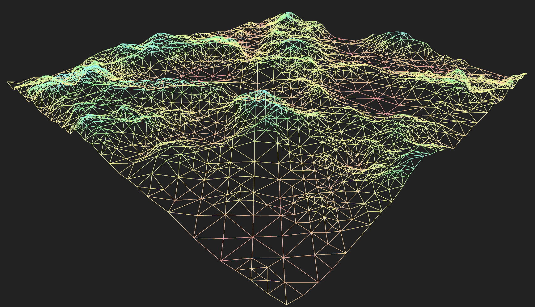
In this post, we will build a simple terrain visualization, while also exploring some of Bevy’s capabilities
Generating a mesh from a heightmap
Usually, terrain is described by a heightmap, usually a squared, grayscale image where each pixel encodes the height of the terrain at (x, z) coordinates
(note: we will work in a Y-up world).

Example Heightmap from Wikipedia
Our application will load the image and turn the heightmap into a mesh.
The simplest approach for doing this would be to partition a plane with a simple pattern of triangles, where the y component of each vector is sampled from the heightmap:
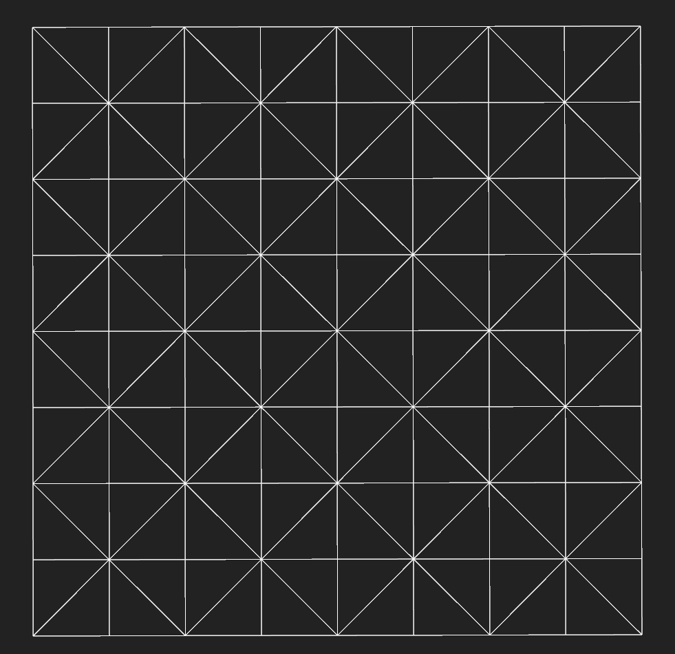
Simple triangle partition
For instance, by applying this approach on the simple heightmap on the left, we obtain the mesh on the right:

Input Heightmap
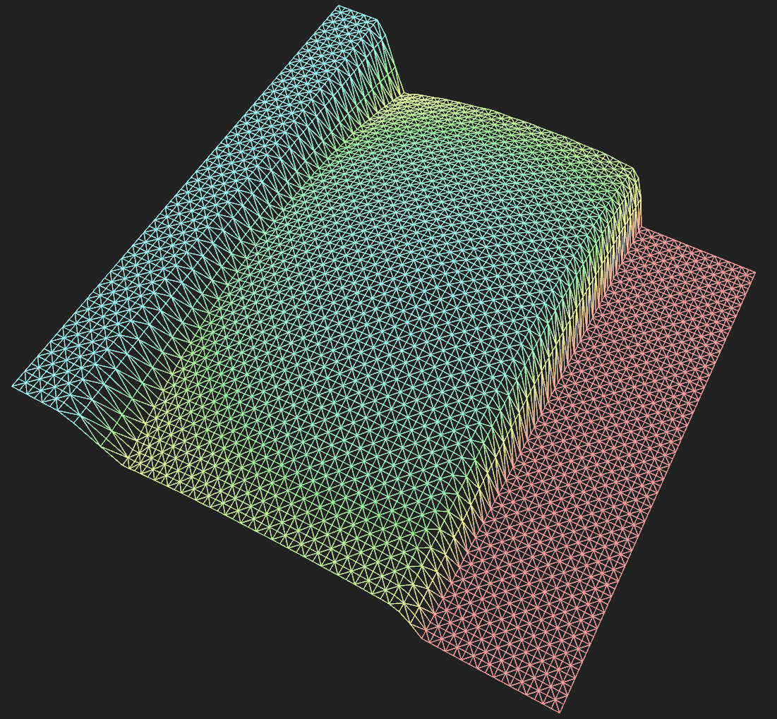
Output Mesh
The above method is perfectly fine in most cases, but if we are going to generate and show multiple meshes (e.g. in an open-world game) the count of triangles is going to increase soon.
Reducing the number of triangles - RTIN
One simple option for reducing the number of triangles consists in approximating parts of the heightmap where the slope is low. This way, planar parts in our mesh will be composed by a minor number of triangles:
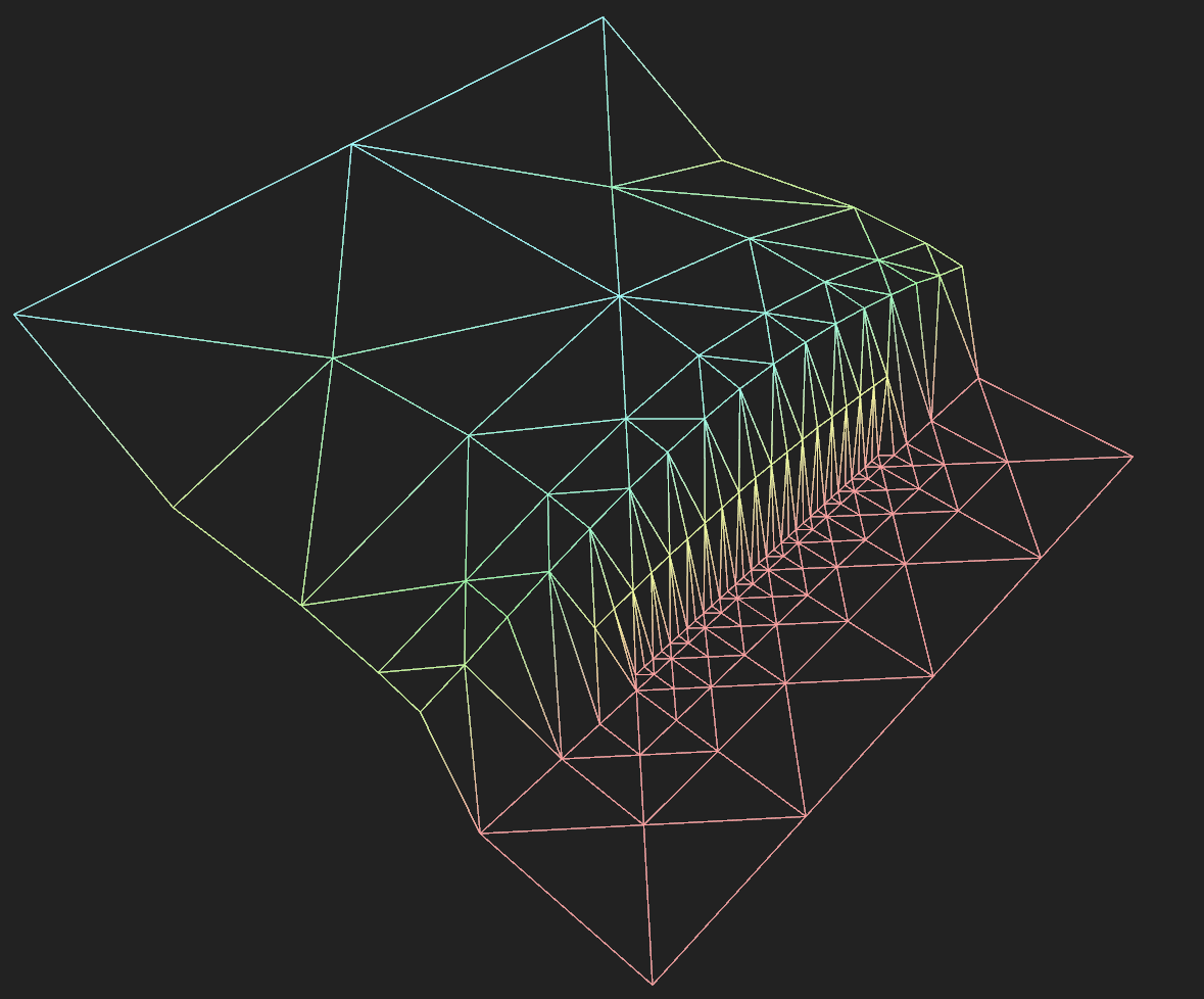
An approximated version of the previous mesh
RTIN (Right-Triangulated Irregular Networks) is one possible algorithm for achieving this. It was nicely described in this Observable article by Vladimir Agafonkin from Mapbox. I have ported his javascript code into rust.
In a nutshell, the algorithm divides the space into two right-triangles recursively (like in a BSP). The obtained hierarchy allows choosing which triangle should be used for the mesh and which triangle should be ignored. I advise reading the article if you want to know how it works.
The function
1 2 | |
accepts the heightmap image data and the maximum allowed error as input. It follows the same process described in the article:
- computes the approximation error for each triangle
- traverses the triangle hierarchy, collecting all the triangles that satisfy the error_threshold
- computes and returns the vertices and indices of each selected triangle:
1 2 3 4 | |
Given an image of side N (where N is a power of 2) the terrain will extend from (0, 0) to (N, N) with a height ranging from 0.0 to 1.0
Build the Bevy mesh
Let’s go back to Bevy now. How can we visualize the triangles that we obtained?
It is very easy to create a new mesh: we choose the primitive topology (i.e. do you want to draw points, triangles, or lines?):
1 2 3 4 5 | |
We then create the vectors that will contain the mesh vertex attributes and indices:
1 2 3 | |
and we fill them starting from the TerrainMeshData obtained above.
Vertices positition and color:
1 2 3 4 5 6 7 8 9 | |
The vertices will have a color proportional to the terrain height. The palette library is used for generating the color gradient.
Indices:
It is useful to show the terrain wireframe for debugging. So we will use different indices depending on whether we want to draw triangles or lines.
1 2 3 4 5 6 7 8 9 10 11 12 13 14 15 16 17 | |
We can now add these vectors to the mesh:
1 2 3 4 5 6 7 8 | |
the set_attribute function accepts an arbitrary string as the first argument. This string will later be referenced in the shader.
Rust type system and Bevy perform all the type conversion for us, so we avoid mangling with byte arrays and pointer casts.
Our mesh is now ready.
Mesh material
Bevy standard material allows to use a texture, but it does not support vertex colors. In order to draw the terrain with color proportional to the height, our shader has to use the TerrainMaterial::ATTRIBUTE_COLOR mesh attribute.
In order to do this, we will use the simple render pipeline and shaders from the mesh_custom_attribute.rs example.
The add_terrain_pipeline function, called during setup, creates and returns a new pipeline:
1 2 3 4 5 6 7 8 9 10 11 12 13 14 15 16 17 18 19 20 21 22 23 24 25 26 27 28 29 30 31 32 33 34 35 36 37 38 | |
Make the mesh available for use
Note: concepts such as Assets, Handle and Resources are described in the Bevy Introduction
We will not add the mesh directly to an Entity. Instead, the mesh will be owned by the Assets asset manager.
Once we move the mesh to the manager, we obtain a Handle in exchange:
1
| |
This Handle is now a clonable reference to the mesh. It is quite useful because, for instance, we can add it to a Bevy Resource:
1 2 3 4 5 | |
So that we can reference later the mesh in any system. For instance, the following system allows us to switch between the shaded and wireframe mesh:
1 2 3 4 5 6 7 8 9 10 11 12 13 14 15 16 17 18 19 20 21 22 23 24 25 26 27 | |
Add the mesh to the scene
Finally, let’s spawn an entity in the scene with the terrain mesh:
1 2 3 4 5 6 7 8 9 10 | |
The terrain mesh will now be visible in the scene:
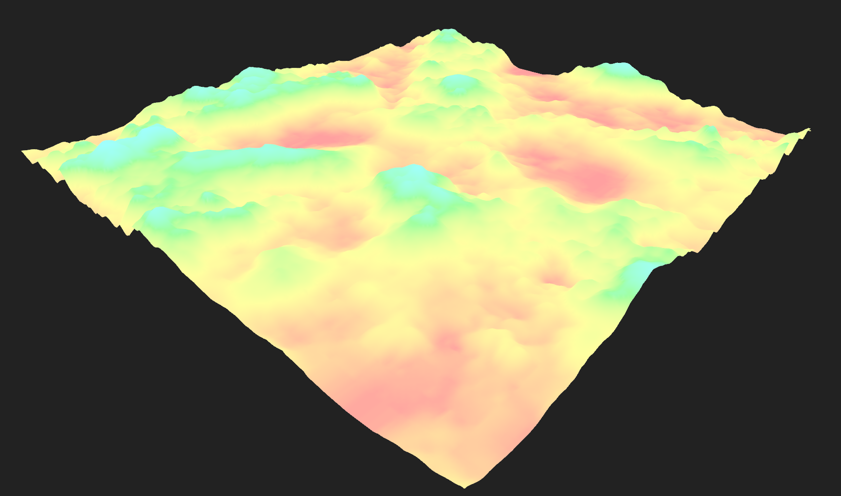
Note that, beyond spawning the MeshBundle, we added a Terrain component. This empty struct actually does nothing at all! However, by adding it to our entity, it works as a tag for referencing this entity in a query. Check the previous definition of switch_mesh_system
1 2 3 4 5 6 7 | |
The terrain_query will only look for entities that contain both a mesh and a terrain component.
Conclusion
After a few days spent playing with this really promising framework I can totally say that using Bevy it’s a nice experience:
- There are enough examples for learning how to use its features
- The ECS system seems very powerful and composable. So far I was always under the impression that I could read and write every part of the application in a clean way, without incurring in borrow checker issues. I don’t know if this will hold true in larger applications, but I am optimistic about it
- Many features are missing right now (e.g. there are just a couple of UI widgets) but the development is pretty active.
In the next post, we will add support for generating random terrain. Until then, you can check the current source code here
Buy a Car With Data - Part 1
I am currently looking for a used car, old but good enough for lasting a few years.
Since I never owned a car, and I lack the anecdotal experience of the car market that many people have, I am likely going to buy a lemon.
Well, let me try to buy a cheap lemon at least.
Autoscout24
I think autoscout24.it is the eBay of used cars in Italy. The website lists many offers from car dealerships and private sellers, with powerful search functionality and a nice looking, website free of ads.

Autoscout24 does offer a RESTful API, but it seems targeted to dealerships.
The best way for getting the data would be to find out how the website or the mobile app uses the API. This is what you want to do if you want to build a program that lasts for more than a few months. However, this could take some time since it involves inspecting the traffic and possibly some reversing.
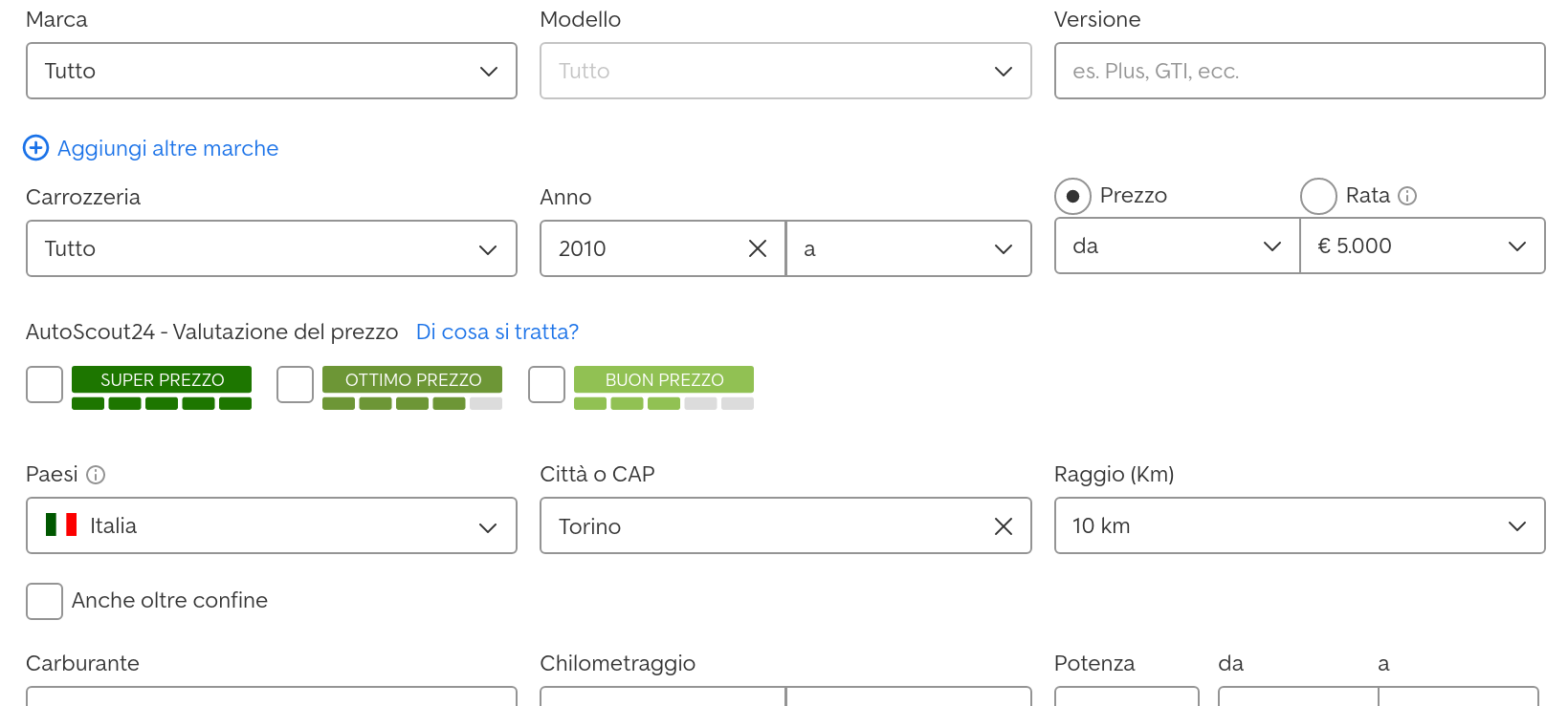
Let’s look at one page from the website instead:

That’s it. A simple table with the details we need. That’s really easy to parse with xpath.
How does the search work? You can choose many fields:
Let’s run the search and inspect the url:
1
| |
all the query parameters are nicely listed in the url. We can easily run any query.
Scrapy
Scrapy is a well-designed python framework for scraping. It provides all the functionalities you need while taking care of the boilerplate code.
You can use its shell to quickly play with xpath and css selectors. Just start it with an url:
1
| |
and you get an IPython environment where the webpage result is ready to be processed.
Once you find out how to get the data you need from the page, you write a Spider. The core of a Spider is just a single parse() function, where you process the response of a GET request.
parse() conveniently uses the yield mechanism for processing each page. After extracting the data, you yield a simple dictionary (representing a single car in our case). This dictionary is appended to a designed output file (e.g. a simple csv).
Then, you yield a new GET request so that you will process the next pages.
Less than 200 lines of python are enough for creating a dataset from autoscout.
Preview of the Dataset
I would have preferred to use Julia for this job, but there are no good scraping libraries currently. So, I will just use it for the data analysis part.
Let’s look at the dataset:
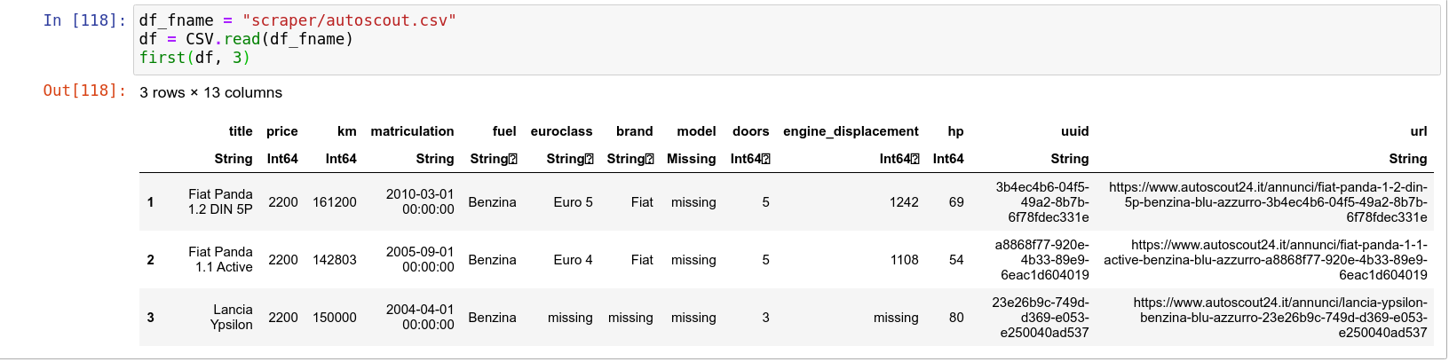
As you can see, I am interested in just a few properties: price, mileage (km), matriculation date, fuel, etc. There is some missing data, we will deal with it later. The dataset includes about 2000 vehicles from sellers in Turin.
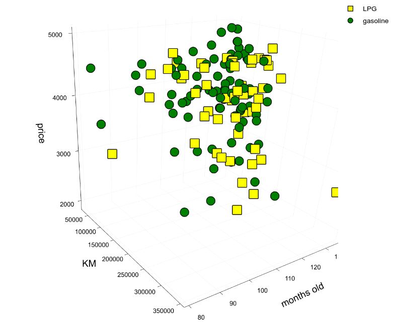
I selected gasoline or LPG vehicles due to traffic restrictions rules in my city. I don’t really care about horsepower or model. Any 10 years old vehicle in the low price range will work for me. However, I will try to use many parameters for building a proper model for price prediction. Every time I will find a car I like, I will compare its price against the predicted one.
Actual analysis will be performed in the next post. Prepare yourself for a heavily technical post full of pie charts and linear regressions.
You can find the scraper code here.
Update 2021-04-01: as usual, my interests shifted on other stuff, so I am not going to write the second part of this blog post :P
A Basic HTTP WebM Server in Rust
I am in the mid of developing a personal project which involves cameras and videostreaming.
While working on this project, I built a small port of the HTTP streaming server of Sebastian Dröge from C into rust:
clynamen/basic_http_webm_server_rust
The server uses a minimal tokio server and the gstreamer-rs library (of which the same S. Dröge is the main contributor).
The main difference between the two version consists in the absence of the multisocketsink element, which is not currently available on rust. This element allows to connect multiple TCP sockets to the gstreamer pipeline, thus providing a simple way for sending the video to multiple clients. In the rust version, this is replaced (probably in a bad way) by an appsink and multiple mpsc queues.
Programmatically Create Function in Julia With Metaprogramming
In the last post, I was evaluating various solutions for generating the Julia-OpenCV bindings I dream of.
I am currently studying how the libcxxwrap library works, in order to check if it fits my requirements. I quickly noticed that it misses the capability of generating function with keywords (see the Github issue). This feature would be really interesting for the binding since OpenCV uses a lot of default and keyword arguments, both of which are nicely supported in python.
But no worries, Julia is a Lisp (or, at least, looks very much like it for many reasons). It should be easy to manipulate function code in order to add defaults, keyword, etc…
Let’s find out how.
Basics
The fundamentals of Julia metaprogramming are explained in the official documentation. You should read that before going further. However, we will start with the easy stuff.
First, let’s write a macro that creates a function.
1 2 3 4 5 6 7 8 9 10 11 | |
What happens when macro make_fn1 is called? We first take value of the macro argument name and convert it into a string, which will be used later for printing. Then, we return an expression that defines a function. The name of the function comes from the same macro argument. When the macro is called, the returned expression is evaluated and thus the function ‘world’ is defined.
We can inspect the expression returned by make_fn1 by using the @macroexpand macro:
1 2 3 4 5 6 | |
Note how in the function declaration we used $(esc(name)) instead of just using $(name). Otherwise, Julia hygiene rules will cause the function to have a random name:
1 2 3 4 5 6 7 8 9 10 11 12 13 14 15 | |
Adding arguments
Ok, we can now generate function with arbitrary names, but we still miss arguments. A possible solution for this was discussed in this discourse thread.
This is the proposed solution:
1 2 3 4 5 6 7 8 9 10 11 12 13 14 15 16 17 18 19 20 21 22 23 24 25 26 27 28 | |
A more complex example
ok, how to add default arguments now?
I have tried to extend the previous solution and failed. I thought it was possible to use this substitution syntax again but I still didn’t figure out how the parser works with the macro output.
However, there is a better way to do this: We can easily manipulate
the AST programmatically,
by composing list of keywords and arguments. Even better, Julia allows you to
inspect the AST via the @dump macro:
1 2 3 4 5 6 7 8 9 10 11 12 13 14 15 16 17 18 19 20 | |
This is pretty handy: you can write an example of the expression you would like to build, inspect its AST and use it as a reference.
Note how the function arguments are just a list of Symbols and Expressions.
Finally, here an example of a macro that defines a function with default and keyword arguments:
1 2 3 4 5 6 7 8 9 10 11 12 13 14 15 16 17 18 19 20 21 22 23 24 25 26 27 28 29 30 31 32 33 34 35 36 37 38 39 40 41 42 43 44 45 46 47 48 49 50 51 52 53 54 55 56 57 58 59 60 61 62 | |
Check out the function generated by the macro:
1 2 3 | |
Conclusions
I think the AST manipulation offers what I need for extending libcxxwrap. Probably it will also be useful during the actual binding generation, allowing to automatically write Julia code that better integrates with the OpenCV interface.
Julia and the Current Status of OpenCV Bindings
Recently the Julia Cxx.jl package came back to life again. The package uses Clang for calling C++ at runtime, possibly making it the most interesting tool for interfacing with a lot of C++ libraries. Since Julia seems really promising for writing Computer Vision algorithms, both for support for Machine Learning and linear algebra in general with high performance, I wanted to try the OpenCV bindings. The idea seemed appealing to quite some people since there are three attempts in this application, that not surprisingly share the same name:
A bit sadly, all three projects seem abandoned now. I am not surprised since both Julia and OpenCV were undergoing many changes in the latest years. Even if bindings are a thin layer of intermixed language code, it is quite a burden to maintain them, especially during the initial phase where no one has a real interest in them.
The OpenCV project itself provides two main bindings, for python and java. I have never used the java binding, but I can assure you the python binding is damn good. Since all the hard work is done by the OpenCV library itself and, elsewhere, by numpy, it is possible to quickly use the complex algorithm offered by OpenCV with C++ performance. These bindings are two extra modules built along with the full source, so they are provided in almost all distributions. Most importantly, being included in the same repo, these bindings are maintained by the same OpenCV developers.
The generation of bindings for other languages, however, is left as an exercise to the reader.
As explained in the official documentation the generation of java and python binding is a quick and dirty process: A python script parses the headers and provides function signatures to a generator, which in turn generates the python (or java) code using template strings and some handcoded files. The process does not seem really modular, and probably today there are better options, especially for the parser (e.g. libclang). But being self-contained and targeted for opencv only, it just works.
As for Julia, lovers of other languages created their own bindings. Just to name a few:
Needless to say, these libraries use different implementation approaches:
- Writing a C library first, and then use the FFI for C
- Wrap the C++ code in a library that can be imported in the desired language.
- Perform a C++ low-level call
Now, all the three Julia implementation cited above seems to have taken the ‘Call C++ code directly’ approach using the Cxx.jl library. After all, clang is powerful enough to do this kind of magic today. It is kind of amazing that compiled and JIT code can talk each other, almost if as if we are using languages built upon a high-level runtime (e.g. C# and VisualBasic on CLR, Java and Scala on the JVM etc…).
So, coming back to the original problem, I would like to improve or write an OpenCV binding for Julia. Still, I am not sure which is the best approach. Using the Cxx.jl library, even if quite elegant and easy to read (since all the ugly stuff stays in the Cxx.jl module itself) involves writing most of the code manually. Whenever functions are added/removed/modified in OpenCV, we need to manually update our bindings. Of course, this happens often, but not so often to be an unmanageable burden (it is the interest of the same OpenCV developers to change the API slowly, without breaking changes).
However the parser approach used by OpenCV makes more sense: Code is generated automatically, except for a few special cases for convenience or performance reason. Only small updates should be required, new functions will be automatically supported, and maybe one day the binding can be merged in the same OpenCV library.
It is hard to chose one of the two paths without prototyping a bit with them. I am currently evaluating the generator approach. I will write about the progress in a new post, hopefully soon.
Experimente Mit Rust - Carsim2d [DE]
Es sind Jahre, Ich wollte etwas mit Rust machen. Als moderner C++ Programmierer zu sein mag ich natürlich Rust: Die Programmiersprache hat die Funktione, die mir am besten gefallen:
- Kompilierzeitprüfungen
- Guter package manager
- Kein garbage-collector, aber ein borrow-checker
Ich hatte die Idee, ein Videospiele zu machen. Aber Ich weiß, Ich brauche mehr Zeit. Rust is nicht so gut als C++ für Videospiele: es ist möglich, Opengl oder Vulkan zu verwenden. Aber es gibt keine or klein library dafür. Zum Beispiel, piston ist eine 2D Game library mit wenige, langsame Funktionen. Amethyst ist vielversprechender. Diese library ist insipiriert aus data-driven Prinzipen und es ist auf eine Entity Component System aufgebaut. Amethyst ist jedoch noch unreif. Die Entwicker versuchen, die Grafik-Engine schenller zu machen. Außerdem würde Ich gerne Opengl vergessen und geh direkt mit Vulkan, aber seine Gemeinschaft ist kleine.
Anstatt ein Videospiele zu machen, suchte Ich nach einer anderen Chance. Ich brauchte ein einfach Fahrzeug-Simulator auf Arbeit mit ROS-Unterstützung. Keine komplexen Grafiken, vielleicht etwas Physik. Die gegenwärtig verfügbar libraries für Rust sollten passen.
Roadsim2D
Roadsim2D ist nur a toy-project. Ich wollte ein Simulator wo man kannt 2D Autos Steuren
Ich schreibe roadsim2D als mein erstes rust Projekt. Ich lerne immer noch, wie die borrow-checker funktioniert. Ich muss sagen: am Anfang, man verschwendet Zeit auch im die einfachesten Dinge. Der compiler hilft dir mit Fehlerbeschreibung, doch die richtige Lösung ist oft spezifisch. Schließlich du musst lernen wie den Programm besser entwürfen. Du lernst wenn du spielst gegen den compiler. Ich habe piston benutzt, um basisch Form zeichen. Die Library steuert geometrisch Transform, so ist es leicht eine Kamera hinzufügen. Ich wollte das nicht kodieren.
Nach dem die Kamera, die Autos wurden hinzugefügt. Ihre Bewegungen folgen die Ackermann Lenkmodell. Ich hatte bald Probleme mit die Borrow-checker: zu viele Variables werden benutzen von zu viele Komponente. Es wurde klar, ich musste den Code umgestalten.
Beim Lesen über Amethyst, Ich habe specs entdeckt. specs ist eine library fur data-oriented programming, ein Paradigma in Game Development sehr bekannt. In diese library, der Programmierer musst Komponenten und Systemen definieren. Komponenten haben data, Systeme haben Code, die die Komponenten verändern. Nicht nur das macht das Programm (potenziell) schneller, das macht alles einfacher als voher zu codieren. Mit specs, es ist explizit, was ist konstant und was kannt änderen. Und du kannst das Leben von Komponenten mit die Entitäten steuern.
Zum Beispiel, schauen wir mal, wie die Physik von Autos ist aktualisiert:
1 2 3 4 5 6 7 8 9 10 11 12 13 14 15 16 17 18 19 20 | |
UpdateCarsSys ist eine Klasse, die die Winkelgeschwindigkeit nach die Ackermann Lenkmodell verändern. Die Klasses tut nur das. Die run() Methode wird bei jedem Frame laufen. In ein System, man kannt eine Query ǘber die Komponenten tun. Dann, kannst du die Ergebnisliste iteriren. Die Komponenten, die du kannst ändern, können mit mut markiert werden.
Links
Self Driving Car Weekly Highlights | Week 08/10/17 - 15/10/17 [En]
General Motors kauft Strobe, solid-state lidar company
Note: This post was translated from English and reviewed with google translate
Dies ist die größte Wichtigste Neuigkeit der Woche. Wir wissen gany genau, dass viele Automobilhersteller mögen solid-state Lidars: Selbst wenn drehend Laser Scanner arbeiten für Forschung und Prototypen (hohe Leistung und Genaugigkeit, aber hohe Kosten) man denkt nicht, sie benutzen in Massenproduktion: rotierende Komponenten halten nicht lange für Anwendung wo Genauigkeit wichtig ist. Du willst nicht, dass die Benutzer ihre Autos zurückbringen, um Lidars zu reparieren
Solid State Lidars wirklich interessant aussehen: keine beweglichen Teile, alles unterbringet in ein Chip, mit geringen Kosten, vergleichbar Genaiugkeit und Reichweite. Aber es gibt ein nur Problem: Wir können sie leicht machen. Trotz sie sind bekannt für einegen Jahren, Solid State Lidars sind schwer zur produzieren. Naturlich dank Investitionen Firma verbessern ihre Lidars von Jahr zur Jahr und das Entwicklung von Konsumgütern ist in der nähe. Du erinnerst dich vielleicht, das Gleiche passiert mit ToF Cameras: Kosten ging von Tausende von Dollars bis ein paar 100$ in ein wenige Jahren (denke an Xbox One Kinect heutzutage).
Es gibt einigen Firmas wie Strobe auf dem Markt. Sie sind noch in ihrer Start-up Phase so es macht Sinn, sie jetzt zu kaufen. Die Entscheidung der Chefs von GM scheint gut wenn man bedenkt, dass andere Firma wird ähnlich tun: Ford investiert in Velodyne im letzen Jahr, Continental kauft ASC, Tesla…
…Nun, Tesls sagt: “Mann, keine Lidars, wir Haben Cameras”.
Und sie sind allein:
Comma.ai shares cool and shiny deep learning videos
Comma.ai teilt neue und glänzend deep learning Videos
Die Firma von George Hotz liebt cameras. Sie sind billig, Man kann finden sie an ein handy und am wichtigsten Sie sind menschliche Augen ähnlich. Und wenn ein Mesnch mit seinen Augen fahren kann, warum sollte dann kein Computer? Das is der gleich Ansatz von Tesla, aber Comma.ai scheint di meinsten seiner Resourcen auf Deep Learning investieren zu.
Zum Beispiel: image segmentation:
This is a single frame no context prediction. Imagine once I get the unsupervised temporal working. Computer vision is unreal! pic.twitter.com/FhoLSkURSF
— comma ai (@comma_ai) September 30, 2017
… oder, du weißt , ersetyen Lidars für Depth Data:
Depth. Trained entirely in simulation. pic.twitter.com/8sY8IATjfn
— comma ai (@comma_ai) October 10, 2017
Es ist interessant das Trainingsdaten wurden geniert mit annotiert Bilden (dank dem adult coloring books Projekt ) und Simulationen
Self Driving Car Weekly Highlights | Week 08/10/17 - 15/10/17 [DE]
So, as you can see it’s long time I don’t write anything on this blog. Despite the intention to write short tutorials, personal opinions, and other technical stuff, this blog was always at the bottom of my always-increasing to-do stack. Why am I then committing myself to write a weekly update on the status of self-driving car development and research? Well, as always there is both a practical argument and a leisure reason: I love talking about this field, which is continuously evolving with exciting changes every day, and I am currently learning German, thus I want to exercise my writing skills daily (which, at the moment, are really bad. But fear not: the posts will be published in English too.) This series of post will be mostly based on news published on other websites or forums. So don’t expect to find the latest rumors but, instead, a review of most important events happened during the week.
General Motors buys Strobe, solid-state lidar company
This is definitely the biggest news of the week. We know quite well that many cars manufacturers have high expectations on solid-state lidars: While rotating laser scanner works for research or prototypes (high performance and accuracy, yet high costs) it is unthinkable to use them in actual user mass-production: Moving an array of laser around accurately requires high manufacturing costs and, most importantly continuously high frequency rotating components do not last long for accurate applications. You don’t want users to bring their car back every year for replacing their faulty lidar.
Solid state lidars look really interesting instead: no moving parts, everything fits in a single chip, lower costs and comparable accuracy and range. Only problem: we are not quite there yet. Despite being known for a few years, solid-state lidars are quite hard to implement. Of course, now that money is poured into, companies are improving their lidars year by year and the development of off-the-shelf consumer solution looks near. You may remember the same happened to ToF cameras: cost decreased from thousands of dollars to a couple 100$ in a few years (think about the Xbox One Kinect today).
There are just a few companies like Strobe around. They are still in their start-up phase and thus it make sense to buy them now. We can agree that the decision of GM’s board seems quite good considering that other companies will probably do something similar in the future: Ford invested in Velodyne last year, Continental bought ASC, Tesla…
…Well, Tesla says “Fuck, we don’t use lidars, we have cameras”.
And they are not alone:
Comma.ai shares cool and shiny deep learning videos
George Hotz’s company loves cameras. They are cheap, they can be found on a mobile phone and most importantly they are the closest thing to an human eye. And if a human can drive a car with his eyes, why shouldn’t a computer? This is the same approach of Tesla, expect that Comma.ai seems to invest most of his resources on deep learning. We know that the Line Keeping Assistant algorithm of openpilot is based on an end-to-end deep neural network, but lately the company is looking to exploit DNN for other scopes:
For instance image segmentation:
This is a single frame no context prediction. Imagine once I get the unsupervised temporal working. Computer vision is unreal! pic.twitter.com/FhoLSkURSF
— comma ai (@comma_ai) September 30, 2017
… or, you know, replacing the previously cited Lidars for depth data
Depth. Trained entirely in simulation. pic.twitter.com/8sY8IATjfn
— comma ai (@comma_ai) October 10, 2017
It is interesting to note how the training data was respectively generated by manually annotated images (thanks to the adult coloring books project ) and simulations.
Outline in Unity With Mesh Transparency
This post was originally published on my previous blog
Here I found a shader for Unity to obtain an outline of a mesh.
http://answers.unity3d.com/questions/141229/making-a-silhouette-outline-shader.html
This shader uses a pass to create a slightly bigger mesh behind the original one. This is a good solution (at least in Unity), but only for convex/non transparent object. The fragments of the outline will indeed appear behind the mesh:
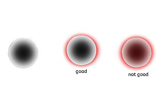
We can remove the fragments behind the mesh modifying the depth buffer with a duplicated object. The original object writes to the z-buffer, so the duplicated object (i.e. the one that act as an outline) will be partially culled by the original one.
In order to obtain this, we can use these shaders:
Transparent shader for the original object
1 2 3 4 5 6 7 8 9 10 11 12 13 14 15 16 17 18 | |
Outline shader for the outline, it will be applied to the duplicated object (Note: this is a mod of the shader quoted at the begin)
1 2 3 4 5 6 7 8 9 10 11 12 13 14 15 16 17 18 19 20 21 22 23 24 25 26 27 28 29 30 31 32 33 34 35 36 37 38 39 40 41 42 43 44 45 46 47 48 49 50 51 52 53 54 55 56 57 58 59 60 61 62 63 64 65 66 67 68 69 70 71 72 73 74 75 76 77 78 79 80 81 82 83 84 85 86 87 88 89 90 91 92 93 94 | |
The result is pretty good:

Finally, here it is a Unity script that automatically creates the outline effect when applied to an object:
1 2 3 4 5 6 7 8 9 10 11 12 13 14 15 16 17 18 19 20 21 22 23 24 25 26 27 28 29 30 31 32 33 34 35 36 37 38 39 40 41 | |
Voxelization in Unity
This post was originally published on my previous blog
A few words on Voxelization and SAT
In this post we will create a script for voxelize any kind of mesh in unity. Voxelization could be useful in physical simulations, terrain representation and every situation where we need to manipulate the hollow inside of a mesh. A great post about Voxelization can be found “here”, on Wolfire blog. The post explains how the voxelization of a triangle mesh is done in Overgrowth, we will use the same method in unity.
The creation of a voxel model that reproduces the mesh is achived trough a 3d grid of cubes and an intersection test for each triangle against each cube. The author states that he uses a AABB-AABB intersection test to check if a cube and a triangle are intersected. This is very fast and appropriate for most situations, but we want the general solution.
A slower but precise way to test the intersection is to use the Separating Axis Theorem. This paper explains the use of the SAT for Triangle-AABB intersection.
An implementation in C++ of this algorithm was written by Mike Vandelay and can be found planet-source-code.com. I rewrote the same code in unityscript.
Basically the SAT works like this
Take 13 axes: 3 axes are the cube face normals, 1 axis is the triangle face normal, 9 are the dot product between the first 3 axes and the triangles edges.
Project the AABB and the triangle on each axis. If the projections intersects on an axis, then the AABB and the triangle are intersected, otherwise they aren’t. here a much more detailed explanation of the SAT.
Now, let’s see how implement all this in unity.
Mesh Voxelization
The complete script for voxelization can be found here on my github.
We are going to use a grid for creating a voxel model. Each Grid is formed by cubes of the same size, these are the grid properties:
1 2 3 4 5 6 7 8 9 10 11 12 13 14 15 16 17 18 19 20 21 22 23 24 25 26 27 | |
All the public method call a CheckBound() function that check if the cube specified by the x, y, z variable is inside the grid, then the real implementation of the method is called. e.g.
1 2 3 4 5 6 7 8 | |
Off course, inside the AABCGrid class and in the possible inheritors, only the unchecked method should be called for faster code.
Creating the voxel shell
Once the grid is defined, we need to ‘set’ all the cubes that are intersected by a triangle of the mesh. This is done in the AABCGrid.FillGridWithGameObjectMeshShell() method.
The result will be a voxel shell, an empty shape that reproduces the mesh.
Ignore the part relative to the normals of the triangles, I’m going to explain that later.
1 2 3 4 5 6 7 8 9 10 11 12 13 14 15 16 17 18 19 20 21 22 23 24 25 26 27 28 29 30 31 32 33 34 35 36 37 38 39 40 41 42 43 44 45 46 47 48 49 50 51 52 53 54 55 56 57 58 59 60 61 62 63 64 65 66 67 68 69 70 71 72 73 74 | |
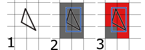
The code finds the AABB of each triangle (2), then performs the SAT intersection test on each cube intersected by AABB (3).
triangles (1) the triangle in the grid. (2) the triangle with its AABB and the AABCs intersected by the AABB. (3) the AABCs intersected by the triangle
Filling the hollow inside
When this method is finished we will have a voxel model that reproduce the mesh. But we have not finished yet, we may need also to know which voxel (AABC) is inside the mesh and which is out. In order to do that we use the scan fill algorithm like the post on overgrowth blog explains, except for a little thing: we don’t start to fill the cube when the normal of the last triangle faces to the left, instead we mark ‘Begin’ and ‘End’ cubes in FillGridWithGameObjectMeshShell(). If the z component of the triangle is positive, we decrease cubeNormalSum[x, y, z] by one, else we increase it. When all the triangles have been processed, a positive cubeNormalSum means that the cube is a ‘Begin’ cube, if it is negative then the cube is an ‘End’ cube.
We can’t just check the normal of the last triangle because we don’t know the order of the triangles, we neither traverse the entire grid during the creation of the voxel shell.
The method FillGridWithGameObjectMesh() does the real scan lining once that FillGridWithGameObjectMeshShell() ends. It traverses all the grid, starting from the cube at 0, 0, 0. If a ‘Begin’ cube is found, an ‘End’ cube is searched. If an ‘End’ cube is found, all the cubes between the last ‘Begin’ and ‘End’ are set.
1 2 3 4 5 6 7 8 9 10 11 12 13 14 15 16 17 18 19 20 21 22 23 24 25 26 27 28 29 30 31 32 33 34 | |
Performance
Performance are mainly determined by the number of triangles in the mesh and the side length of the AABCs. Here they are some of the tests made on my laptop:
Laptop specs: HP g6-1359el Intel Core i5-2450M - 2,5 GHz AMD Radeon HD 7450M
First Test
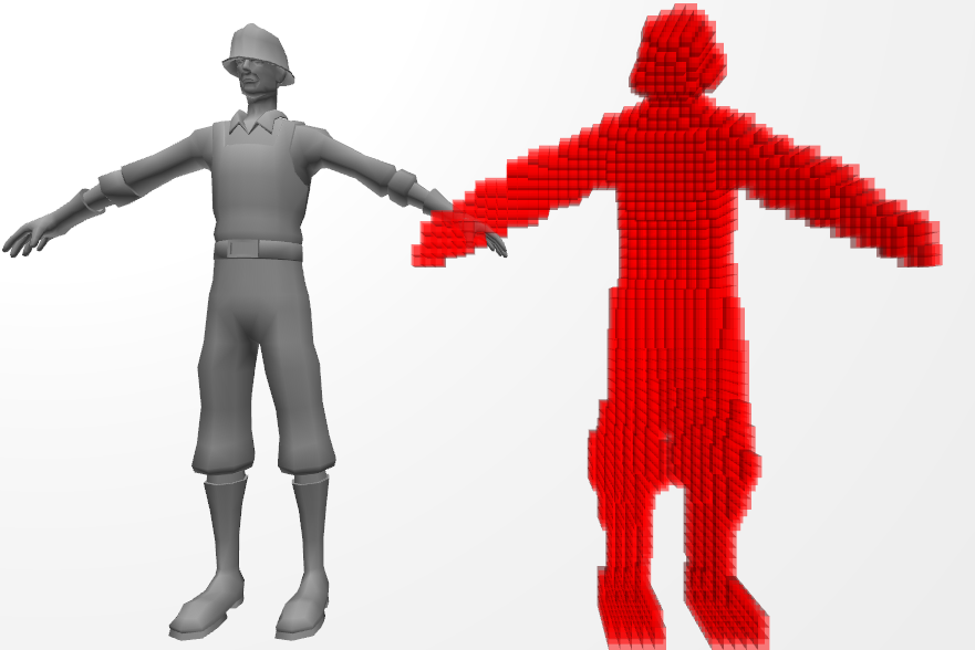
Mesh: construction_worke Time spent: 0.4051636s Triangles: 4020 Cube side: 0.05
Second Test
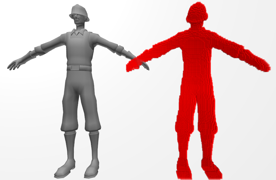
Mesh: construction_worker Time spent: 1.088864s Triangles: 4020 Cube side: 0.02
Third Test
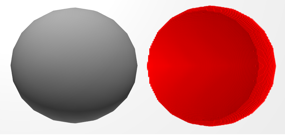
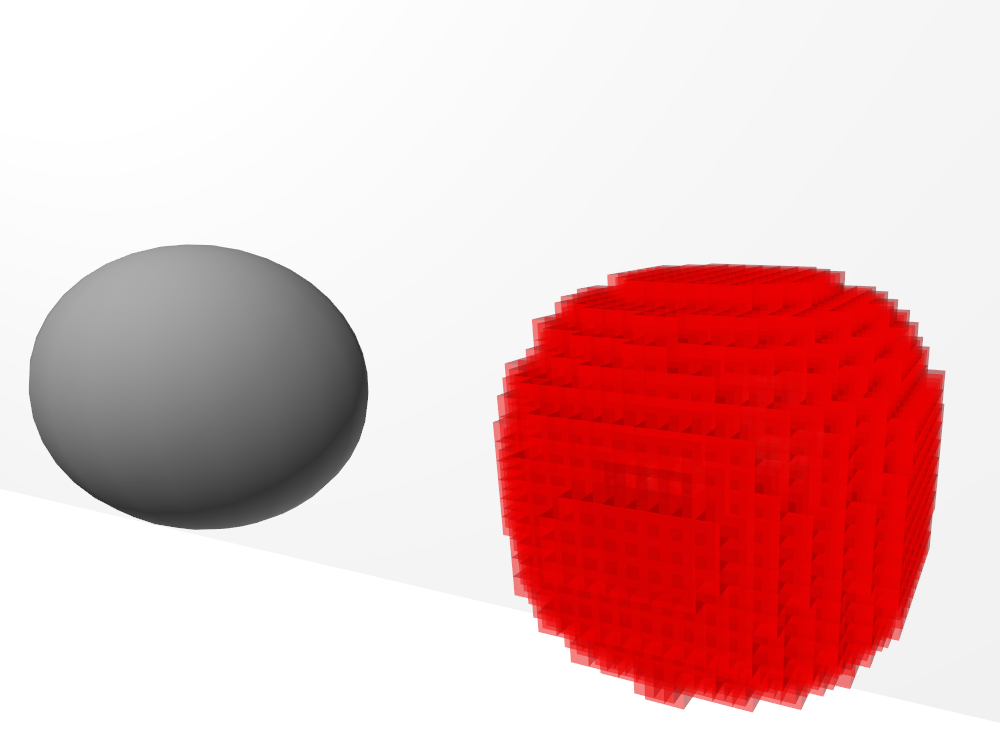
Mesh: sphere
Time spent: 1.926165s Triangles:760 Cube side: 0.03
Memory could be saved storing cubeSet using a 3D bitarray class and cubeNormalSum using a 3D array of bytes
Try it yourself
For testing purpose there is also a VoxelizationTest.js script on my github. Attach it to an object with a mesh to try this voxelization script. Remember to enable Gizmos in the game window, otherwise the AABCs will not appear!